Coming into the week I was excited because this was one of the weeks I was most looking forward too because PCB have always seemed like
something that I would never understand.
1. I started by opening eagle and adding the Fab Library to the Libraries part of Eagle so I would be able to access the parts and footprints.
This was really annoying. I started by going to options then going to directories then linking where I am keeping the fab folder. Then I right
click on the folder in eagle then click use all.
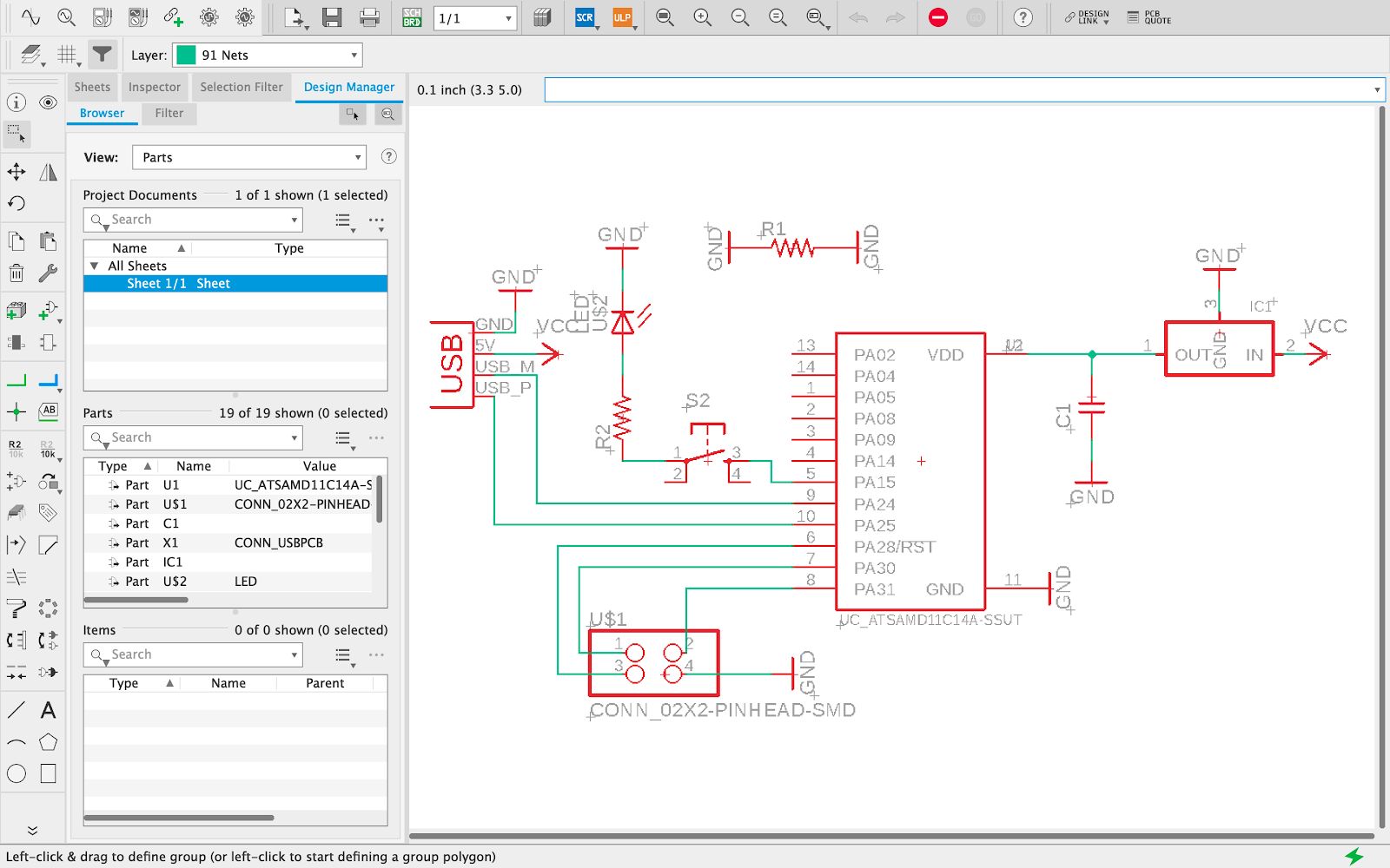
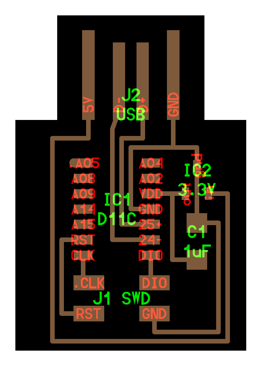
2. Next I made a schematic. I opened up the SAMD11C Echo board image.
From that I was able to pull in all the components I needed into the schematic page of eagle. That inlcuded: SAMD11C, 2x2 pin header, 1uF Capacitor, and
voltage regulator. I knew we had to do something with a button and LED as well but I wanted to see if I could recreate the board first. But in the end I
added a button, an LED, a 100 Ohm resistor and a 0 Ohm resistor. In the schematic page of eagle I then tried to orient all the components so the connects
would be as short as possible. I used net to connect the different components. For the SAMD11C I needed to look at the data sheet to figure out what each
pin does because the footprint in the schematic does not always look like it does in the Eagle board view. In order to make the schematic more readable
I got a componenet named ground and connected it to all the grounds which connected it on the board but made it look simpler. I did the same will VCC of 5V.
I also made connections that crossed each other the same name which connected them what I went to the board view.
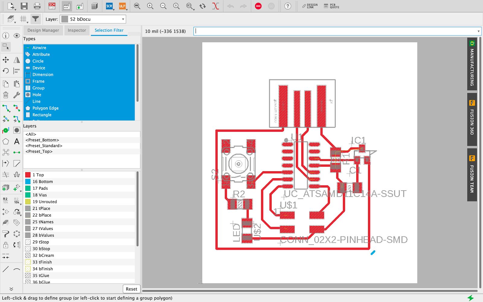
3. Next we go into board view to try to work with airrouting. This is where the art of the work comes in. I started by setting up the components in a way that I
think that they should be laid out. In this case I was copying the board image.
Once the components where set up I moved the button to where I thought it would be easiest once I started routing the wires. This part I though was going to much harder than it was.
It was really just using some creativity to find clever ways to make the traces fit. I did this all on the top layer. I could add vias to add grounds which would
make the board itself less busy but I will know this for the future. When trying to make the outline I had used polygon on the bottom layer originally. This caused
some problems because it would become a dotted line. And when I exported as a PNG it also exported as a dotted line. So mods would cut dots instead of holes. I tried
to be clever and use a line on the bottom layer then export as a PNG but that caused mods to but out a literally line-square thing. In the end I moved the polygon to milling
layer and in mods inversed the colors it worked. One of the biggest problems that occured was that after exporting the image as a PNG it was exporting at twice the size that
it said it should be outputting. So in mods I needed to scale down to from 1000 to 1800. But in reality I should have scaled down to 2000 because it was becoming
twice what I expected.
How I did it:
Display none
Choose top layer
Export image
Monochrome, 1000 DPI
Display none
Choose milling layer
Export image
Monochrome, 1000 DPI
a. I set the trace width the 16
b. I set the design rules to everything to 16mm
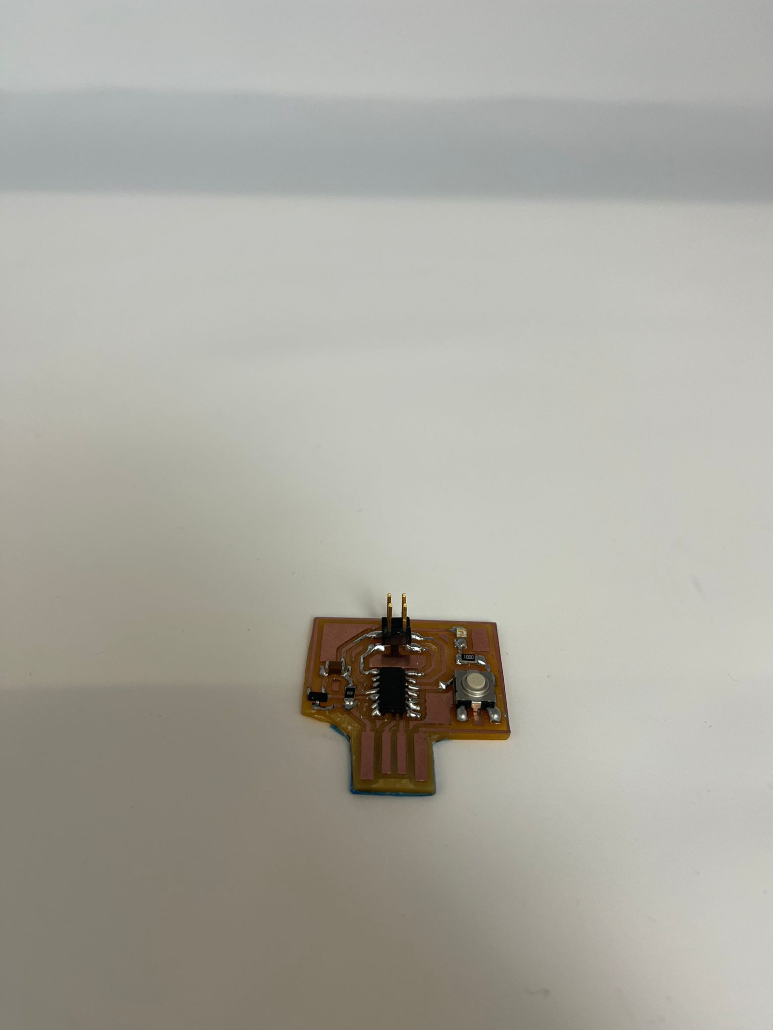
4. Soldering was after printing. This went much smoother than Week 2. This was because the steps I took before I started
soldering. I started by setting up my set up. I turned on soldering pen-thing, turned on the light, turned on the fan, and cut a piece of solder wire I was
going to use. I set up the PCB under the microscope as well. To solder a piece down, I would apply solder to one pad then solder it onto that pad then, solder
the rest of the pads. I messed up a couple times but gotten pretty good using the copper thing to fix my mistakes.
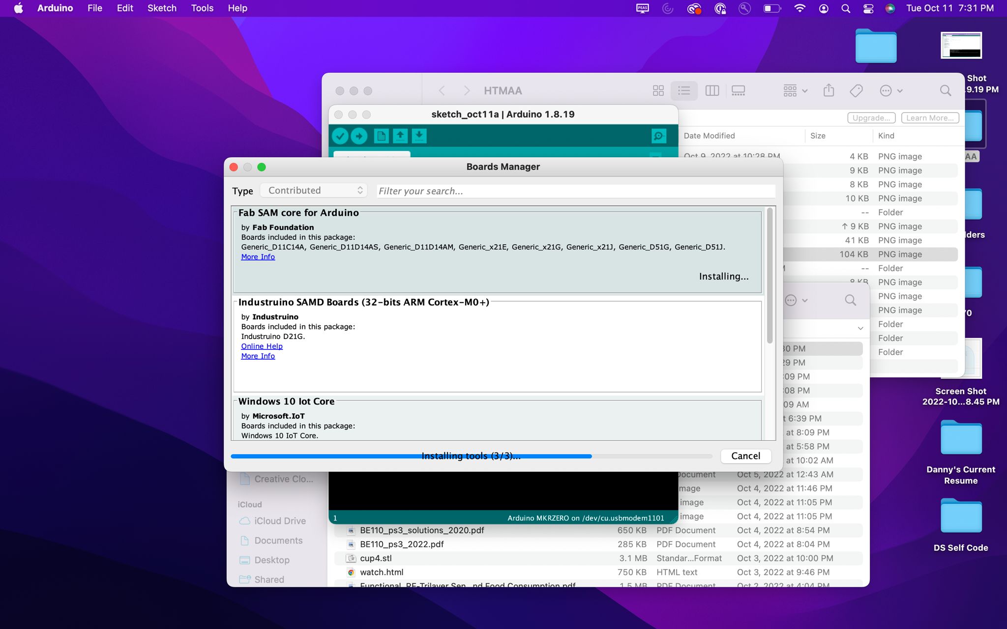
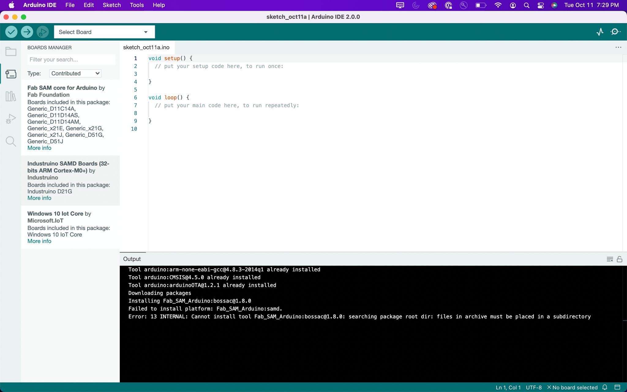
5. Next came programming. I started by taking the programmer I used last week and using that to bootload the SAMD11C on the echo board. To do that I plugged my
programmer and echo board into a power source then ran openocd from atsamd11-master-bootloader github that I pulled to my local device. I then went on this
github to add the atsam11d to my arduino boards. Once that was added
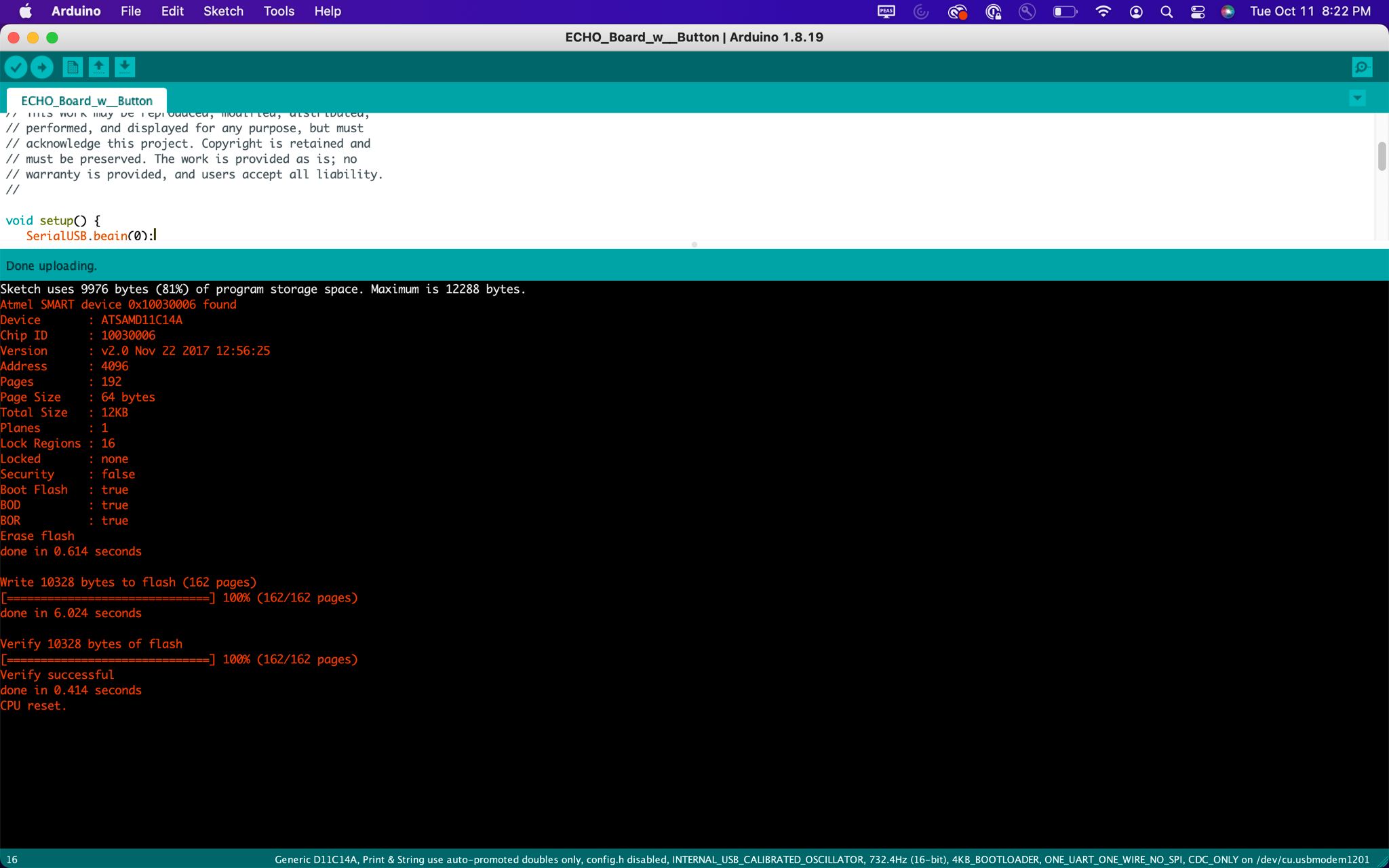
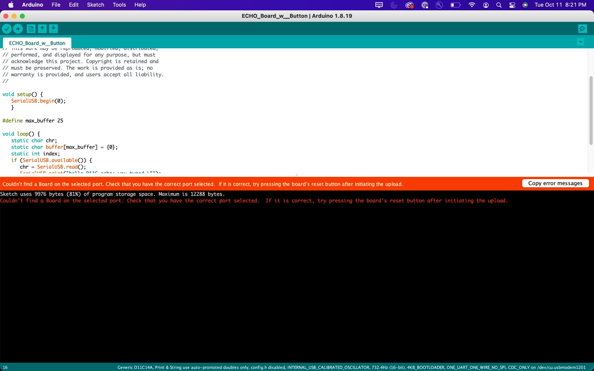
I got the echo.ino from the website. After that was uploaded to my board I tried
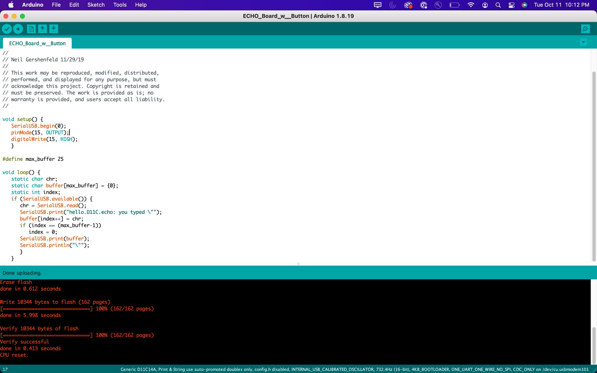
to add get my button to function. I talked with Quinton and he very graciously described that I now can do so much by essentially coding in arduino. By using pinMode function.
The pin that I set I found on the ATSAMD11c Datasheet. In the end I was able
to get a board that uses a button to turn on and off an LED.
To add the atsamd11c board to arduino: